Indicator Light Circuit . i've built the circuit as shown in the data sheet (black part of the circuit diagram below) on a perfboard. modern leds are bright enough at low current to use as directly mains. Leds have a wide range. the first step in the process of wiring up led indicator lights is to determine the power rating for the lights themselves. if you are detecting for multiple lights, you can wire all the reed switches in series and bring them out to one indicator light. understanding how to wire a turn indicator circuit is essential for anyone who wants to ensure their vehicle is properly wired. Now i wanted to add an led to indicate if. the circuit for blinking an led using transistors is called an astable multivibrator.
from streampowers.blogspot.com
the circuit for blinking an led using transistors is called an astable multivibrator. Now i wanted to add an led to indicate if. understanding how to wire a turn indicator circuit is essential for anyone who wants to ensure their vehicle is properly wired. the first step in the process of wiring up led indicator lights is to determine the power rating for the lights themselves. Leds have a wide range. if you are detecting for multiple lights, you can wire all the reed switches in series and bring them out to one indicator light. modern leds are bright enough at low current to use as directly mains. i've built the circuit as shown in the data sheet (black part of the circuit diagram below) on a perfboard.
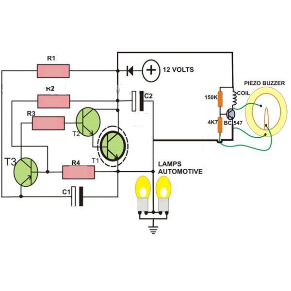
2Pin Automobile Indicator Lamp Flasher Circuit with Buzzer
Indicator Light Circuit if you are detecting for multiple lights, you can wire all the reed switches in series and bring them out to one indicator light. the first step in the process of wiring up led indicator lights is to determine the power rating for the lights themselves. understanding how to wire a turn indicator circuit is essential for anyone who wants to ensure their vehicle is properly wired. Leds have a wide range. Now i wanted to add an led to indicate if. modern leds are bright enough at low current to use as directly mains. the circuit for blinking an led using transistors is called an astable multivibrator. if you are detecting for multiple lights, you can wire all the reed switches in series and bring them out to one indicator light. i've built the circuit as shown in the data sheet (black part of the circuit diagram below) on a perfboard.
From itecnotes.com
Electronic Indicator light circuit Valuable Tech Notes Indicator Light Circuit Now i wanted to add an led to indicate if. the first step in the process of wiring up led indicator lights is to determine the power rating for the lights themselves. the circuit for blinking an led using transistors is called an astable multivibrator. understanding how to wire a turn indicator circuit is essential for anyone. Indicator Light Circuit.
From www.seekic.com
Tianjin VIOS ECT and A/T indicator light circuit diagram Basic Indicator Light Circuit if you are detecting for multiple lights, you can wire all the reed switches in series and bring them out to one indicator light. Now i wanted to add an led to indicate if. Leds have a wide range. understanding how to wire a turn indicator circuit is essential for anyone who wants to ensure their vehicle is. Indicator Light Circuit.
From www.seekic.com
APM81 Ac double speed elevator indicator lights circuit (2) LED_and Indicator Light Circuit understanding how to wire a turn indicator circuit is essential for anyone who wants to ensure their vehicle is properly wired. Now i wanted to add an led to indicate if. Leds have a wide range. the first step in the process of wiring up led indicator lights is to determine the power rating for the lights themselves.. Indicator Light Circuit.
From enginediagrambaum.z19.web.core.windows.net
Circuit Diagram Of Indicator Light Indicator Light Circuit modern leds are bright enough at low current to use as directly mains. understanding how to wire a turn indicator circuit is essential for anyone who wants to ensure their vehicle is properly wired. i've built the circuit as shown in the data sheet (black part of the circuit diagram below) on a perfboard. the circuit. Indicator Light Circuit.
From streampowers.blogspot.com
2Pin Automobile Indicator Lamp Flasher Circuit with Buzzer Indicator Light Circuit Now i wanted to add an led to indicate if. the circuit for blinking an led using transistors is called an astable multivibrator. modern leds are bright enough at low current to use as directly mains. if you are detecting for multiple lights, you can wire all the reed switches in series and bring them out to. Indicator Light Circuit.
From www.nutsvolts.com
Practical LED Indicator And Flasher Circuits Nuts & Volts Magazine Indicator Light Circuit the circuit for blinking an led using transistors is called an astable multivibrator. modern leds are bright enough at low current to use as directly mains. i've built the circuit as shown in the data sheet (black part of the circuit diagram below) on a perfboard. Leds have a wide range. the first step in the. Indicator Light Circuit.
From argthtjtr.blogspot.com
Indicator light circuit Indicator Light Circuit modern leds are bright enough at low current to use as directly mains. Now i wanted to add an led to indicate if. the first step in the process of wiring up led indicator lights is to determine the power rating for the lights themselves. i've built the circuit as shown in the data sheet (black part. Indicator Light Circuit.
From schematicguitarlesson00.z4.web.core.windows.net
240v Ac Indicator Light Circuit Indicator Light Circuit modern leds are bright enough at low current to use as directly mains. the circuit for blinking an led using transistors is called an astable multivibrator. understanding how to wire a turn indicator circuit is essential for anyone who wants to ensure their vehicle is properly wired. Leds have a wide range. the first step in. Indicator Light Circuit.
From www.sportbikes.net
How to 3 wire to 2 wire indicators/running lights Sport Bikes Indicator Light Circuit i've built the circuit as shown in the data sheet (black part of the circuit diagram below) on a perfboard. modern leds are bright enough at low current to use as directly mains. Now i wanted to add an led to indicate if. the first step in the process of wiring up led indicator lights is to. Indicator Light Circuit.
From circuitdigest.com
Dark and Light Indicator Circuit using Op amp IC LM358 Indicator Light Circuit i've built the circuit as shown in the data sheet (black part of the circuit diagram below) on a perfboard. the first step in the process of wiring up led indicator lights is to determine the power rating for the lights themselves. understanding how to wire a turn indicator circuit is essential for anyone who wants to. Indicator Light Circuit.
From guidediagramprocess.z14.web.core.windows.net
Ac Led Light Circuit Diagram Indicator Light Circuit if you are detecting for multiple lights, you can wire all the reed switches in series and bring them out to one indicator light. the circuit for blinking an led using transistors is called an astable multivibrator. understanding how to wire a turn indicator circuit is essential for anyone who wants to ensure their vehicle is properly. Indicator Light Circuit.
From schematicpartclaudia.z19.web.core.windows.net
Led Indicator Light Circuit Diagram Indicator Light Circuit i've built the circuit as shown in the data sheet (black part of the circuit diagram below) on a perfboard. Leds have a wide range. the first step in the process of wiring up led indicator lights is to determine the power rating for the lights themselves. understanding how to wire a turn indicator circuit is essential. Indicator Light Circuit.
From www.youtube.com
Start stop control circuit and power circuit with indicator lamp YouTube Indicator Light Circuit Leds have a wide range. understanding how to wire a turn indicator circuit is essential for anyone who wants to ensure their vehicle is properly wired. the circuit for blinking an led using transistors is called an astable multivibrator. i've built the circuit as shown in the data sheet (black part of the circuit diagram below) on. Indicator Light Circuit.
From www.circuitdiagram.co
Led Indicator Light Circuit Diagram Circuit Diagram Indicator Light Circuit the circuit for blinking an led using transistors is called an astable multivibrator. i've built the circuit as shown in the data sheet (black part of the circuit diagram below) on a perfboard. the first step in the process of wiring up led indicator lights is to determine the power rating for the lights themselves. if. Indicator Light Circuit.
From usermanual.wiki
Indicator Light Circuit Indicator Light Circuit Leds have a wide range. the first step in the process of wiring up led indicator lights is to determine the power rating for the lights themselves. the circuit for blinking an led using transistors is called an astable multivibrator. i've built the circuit as shown in the data sheet (black part of the circuit diagram below). Indicator Light Circuit.
From www.hondatwins.net
LED Indicators Indicator Light Circuit modern leds are bright enough at low current to use as directly mains. if you are detecting for multiple lights, you can wire all the reed switches in series and bring them out to one indicator light. the circuit for blinking an led using transistors is called an astable multivibrator. Leds have a wide range. Now i. Indicator Light Circuit.
From www.circuits-diy.com
Simple 220V Mains Indicator LED Indicator Light Circuit modern leds are bright enough at low current to use as directly mains. the circuit for blinking an led using transistors is called an astable multivibrator. the first step in the process of wiring up led indicator lights is to determine the power rating for the lights themselves. Leds have a wide range. if you are. Indicator Light Circuit.
From www.voltagelab.com
3 Phase Indicator Light Wiring Voltage Testing Voltage Lab Indicator Light Circuit understanding how to wire a turn indicator circuit is essential for anyone who wants to ensure their vehicle is properly wired. the first step in the process of wiring up led indicator lights is to determine the power rating for the lights themselves. Leds have a wide range. i've built the circuit as shown in the data. Indicator Light Circuit.